
How a Processor Moves Data has more than 100 billion transistors. Taking a walk through one of them could get a person hopelessly lost. Old or new, however, how a processor performs its most basic functions hasn’t changed.
They may have as many as eight execution cores and multiple caches—you can look at those on pages XXX–xxx—but, like the old single-core Pentium III processor illustrated here, they all face the same problem of how to move data quickly and with nary a hitch.
Processor datapath in computer architecture | Detailed data path of (How a Processor Moves Data ) a typical register-based CPU
1. A processor and its integrated cache share the same interface to the computer’s information. Program code or data manipulated by that code moves in and out of the chip at the PC’s maximum bus speed. Much of a computer’s architecture is structured to alleviate the bus bottleneck by minimizing the times a clock cycle—the shortest time in which a computer can do anything—ticks away without the processor completing an operation.
2. When information enters the processor through the bus interface unit (BIU), the BIU duplicates the information and sends one copy to the CPU’s closest data caches that are housed directly within the processor core. The BIU sends program code to the Level 1 instruction cache, or I-cache, and sends data to be used by the code to another L1 cache, the data cache (D-cache).
3. While the fetch/decode unit is pulling in instructions from the I-cache, the branch target buffer (BTB) compares each instruction with a record in a separate set-aside buffer to see whether any instruction has been used before.
The BTB is looking in particular for instructions that involve branching, a situation in which the program’s execution could follow one of two paths. If the BTB finds a branch instruction, it predicts, based on past experience, which path the program will take. The predictions are better than 90 percent accurate.
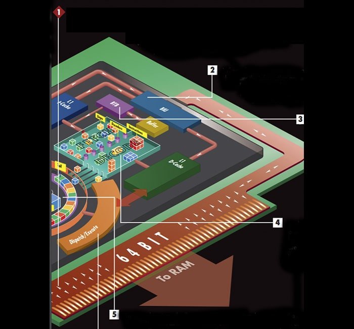
4. As the fetch/decode unit pulls instructions in the order predicted by the BTB, three decoders working in parallel break up the more complex instructions into μops, which are smaller micro-operations. The dispatch/execution unit processes several μops faster than it processes a single higher-level instruction.
5. The decode unit sends all μops to the instruction pool, also called the reorder buffer. This contains two arithmetic logic units (ALUs) that handle all calculations involving integers. The ALUs use a circular buffer, with a head and tail, that contains the μops in the order in which the BTB predicted they would be needed.
6. The dispatch/execute unit checks each μop in the buffer to see whether it has all the information needed to process it, and when it finds a μop ready to process, the unit executes it, stores the result in the micro-op itself, and marks it as done.
7. If a μop needs data from memory, the execute unit skips it, and the processor looks for the information first in the nearby L1 cache. If the data isn’t there, the processor checks the next cache level, L2 in this case. Cache size and organization vary based on the specific processor design, but each level of cache increases in both capacity and time needed to fetch data from it.
8. Instead of sitting idle while that information is fetched, the execute unit continues inspecting each μop in the buffer for those it can execute. This is called speculative execution because the order of μops in the circular buffer is based on the BTB’s branch predictions.
The unit executes up to five μops simultaneously. When the execution unit reaches the end of the buffer, it starts at the head again, rechecking all the μops to see whether any have finally received the data they need to be executed.
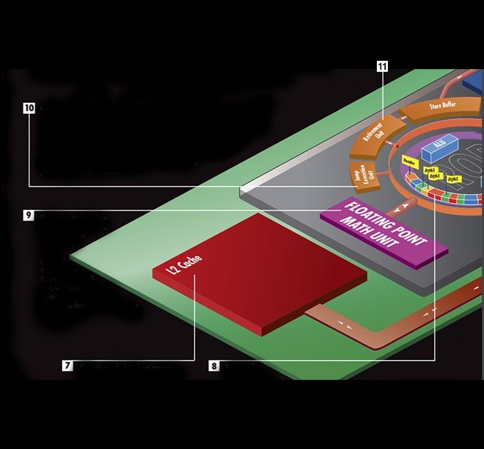
9. If an operation involves floating-point numbers, such as 3.14 or .33333, the ALUs hand off the job to the floating-point math unit, which contains processing tools designed to manipulate floating-point numbers quickly.
10. When a μop that had been delayed is finally processed, the execute unit compares the results with those predicted by the BTB. Where the prediction fails, a component called the jump execution unit (JEU) moves the end marker from the last μop in line to the μop that was predicted incorrectly.
This signals that all μops behind the end marker should be ignored and can be overwritten by new μops. The BTB is told that its prediction was incorrect and that information becomes part of its future predictions.
11. Meanwhile, the retirement unit is also inspecting the circular buffer. It first checks to see whether the μop at the head of the buffer has been executed. If it hasn’t, the retirement unit keeps checking it until it has been processed.
Then, the retirement unit checks the second and third μops. If they’re already executed, the unit sends all three results—its maximum—to the store buffer. There, the prediction unit checks them out one last time before they’re sent to their proper place in the system RAM.
If you want to learn how a processor moves data all over the system, please let us know.